
DescriptionRTE performs 2-D and 3-D thermal analysis of regeneratively cooled rocket thrust chambers and nozzles. The program uses GASP (GAS Properties) and CET (Chemical Equilibrium with Transport Properties) for evaluation of the coolant and hot gas properties, respectively. Inputs consist of fuel/oxidant mixtures and flow rates, chamber pressure, coolant entrance temperature and pressure, dimensions of the engine, materials and number of nodes. | Pricing Year - $3000 Month - $600 Week - $300 Day - $150 Initiation Fee - $500 Export controlled |
 | |
| This program allows temperature variations in axial, radial and circumferential directions. It provides a listing of nodal temperatures, rates of heat transfer, and hot gas and coolant thermal and transport properties. The mixture ratio at each station can be calculated using ROCCID (ROCket Combustor Interactive Design and Analysis Computer Program). ROCCID has been modified to take RTE input and make the mixture ratio variable along the thrust chamber. Thermal radiation from hot gases within the chamber is also included in the analysis. The exchange factors for radiation calculations are evaluated using an external module (RTE_DEF, Rocket Thermal Evaluation_Discrete Exchange Factor) which can be input to the main rocket thermal evaluation code. | |
| This code can be used for both regeneratively and radiatively cooled engines. For regeneratively cooled engines, however, its application is limited to those engines with single stage cooling and rectangular cooling channels. The user has the option of bypassing the hot-gas-side calculations and directly inputting gas side fluxes. This feature can be used to link RTE to a boundary layer program for the hot-gas-side heat flux calculation. | |
SUMMARY OF THE NUMERICAL MODEL AND SOME SAMPLE RESULTS | |
| The Rocket Thermal evaluation code is based on the geometry of a typical regeneratively-cooled engine similar to that shown in Figure 1. | |
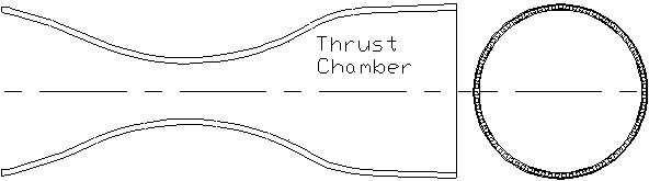 Figure 1: Configuration of a typical regeneratively cooled rocket thrust chamber and nozzle | |
| The wall can consist of three layers (see Figure 2): a coating, the channel, and the closeout. These three layers can be different materials or the same material. The number of cooling channels in the wall are also specified by the user. | |
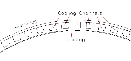 Figure 2: Configuration of a typical regeneratively cooled thrust chamber and nozzle wall | |
| For the numerical procedure, the rocket thrust chamber and nozzle are subdivided into a number of stations along the longitudinal direction, as shown in Figure 3. The thermodynamic and transport properties of the combustion gases are evaluated using the chemical equilibrium composition computer program developed by Gordon and McBride (CET, Chemical Equilibrium with Transport properties). The GASP (GAS Properties) or WASP (Water And Steam Properties) WASP programs are implemented to obtain coolant thermodynamic and transport properties. Since the heat transfer coefficients of the hot gas and coolant sides are related to surface temperatures, an iterative procedure is used to evaluate heat transfer coefficients and adiabatic wall temperatures. | |
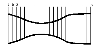 Figure 3: A rocket thrust chamber and nozzle subdivided into a number of stations | |
| The temperature distribution within the wall is determined via an axial marching technique starting from station 1 to the last station. The program marches axially from one station to another. At each station a two-dimensional finite element model is used to determine the temperature distribution along the radial and circumferential directions. The axial heat conduction acts as internal heat source in the two-dimensional heat conduction model. When the axial march is completed, comparison is made between the results of the present march and that of the previous one to see if the convergence criteria in the axial direction has been met. If it is not met, the code starts again at the first station and makes another axial march. The process continues until convergence is achieved. A detailed description of this numerical model is outlined in the manual of RTE. Figure 4 shows some sample results of the wall temperature distribution at various locations in the engine. Note that the temperature distribution is given for one cell and the indentation at the left is the cooling channel. | |
  Figure 4. Temperature distribution at different locations within the chamber wall. | |
| Similar temperature distributions can be generated for all stations along the engine. In addition to the wall temperature distribution the program provides all transport and thermodynamics properties for coolant and combustion gases. | |